Configure VLANs and EtherChannel
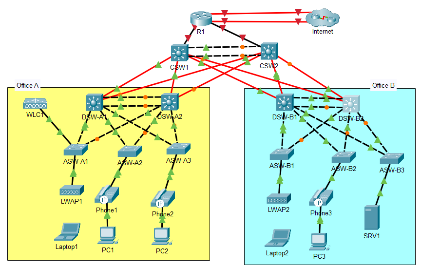
- In Office A, configure a Layer-2 EtherChannel named PortChannel1 between DSW-A1 and DSW-A2 using a Cisco-proprietary protocol. Both switches should actively try to form an EtherChannel.
Use the Cisco proprietary PAGP. Notice that this says that both switches should actively try to form an EtherChannel. PAgP has two modes: desirable and auto. This means we should configure both sides to use the desirable mode, which actively tries to form an EtherChannel. Auto mode will form an EtherChannel with a neighbor in desirable mode, but doesn’t try to form an EtherChannel itself.
Confirm which interfaces are connected to the switch for the uplink, you can use show cdp neighbors to find it is interfaces 4 and 5:
DSW-A1(config)#do show cdp nei
Capability Codes: R - Router, T - Trans Bridge, B - Source Route Bridge
                  S - Switch, H - Host, I - IGMP, r - Repeater, P - Phone
Device ID    Local Intrfce   Holdtme    Capability   Platform    Port ID
CSW1         Gig 1/1/1        170                    3650        Gig 1/1/1
CSW2         Gig 1/1/2        170                    3650        Gig 1/1/1
DSW-A2       Gig 1/0/4        173                    3650        Gig 1/0/4
DSW-A2       Gig 1/0/5        173                    3650        Gig 1/0/5
ASW-A1       Gig 1/0/1        170            S       2960        Gig 0/1
ASW-A3       Gig 1/0/3        170            S       2960        Gig 0/1
ASW-A2       Gig 1/0/2        170            S       2960        Gig 0/1
Configure an EtherChannel with PaGP
Configure the port channel on DSW-A1, and the same commands on DSW-A2:
DSW-A1#conf t
DSW-A1(config)#int range g1/0/4-5
DSW-A1(config-if-range)#channel-group 1 mode desirable
DSW-A1(config-if-range)#
Creating a port-channel interface Port-channel 1
Confirm that the port channel has been established on each device:
DSW-A2(config-if-range)#do show etherchannel summary
Flags:  D - down        P - in port-channel
        I - stand-alone s - suspended
        H - Hot-standby (LACP only)
        R - Layer3      S - Layer2
        U - in use      f - failed to allocate aggregator
        u - unsuitable for bundling
        w - waiting to be aggregated
        d - default port


Number of channel-groups in use: 1
Number of aggregators:           1

Group  Port-channel  Protocol    Ports
------+-------------+-----------+----------------------------------------------

1      Po1(SU)           PAgP   Gig1/0/4(P) Gig1/0/5(P)
- In Office B, configure a Layer-2 EtherChannel named PortChannel1 between DSW-B1 and DSW-B2 using an open standard protocol. Both switches should actively try to form an EtherChannel.
LACP has two modes: active, which is like PAgP’s desirable mode, and passive, which is like PAgP’s auto mode. Like step 1, step 2 says that both switches should actively try to form an EtherChannel, so we’ll use active mode.
Configure an EtherChannel with LACP
DSW-B2(config)#int range g1/0/4-5
DSW-B2(config-if-range)#channel-group 1 mode active
DSW-B2(config-if-range)#
Creating a port-channel interface Port-channel 1

DSW-B2(config-if-range)#do show etherchannel summary

Number of channel-groups in use: 1
Number of aggregators:           1

Group  Port-channel  Protocol    Ports
------+-------------+-----------+----------------------------------------------

1      Po1(SU)           LACP   Gig1/0/4(P) Gig1/0/5(P)
- Configure all links between Access and Distribution switches, including the EtherChannels, as trunk links.
a. Explicitly disable DTP on all ports with switchport nonegotiate. This is best security practice, to prevent any automatic trunk links forming.
b. Set each trunk’s native VLAN to VLAN 1000 (unused). This is good security practice, as the native VLAN can make the LAN vulnerable to VLAN hopping attacks.
c. In Office A, allow VLANs 10, 20, 40, and 99 on all trunks:
Configure VLANs on Switch Ports
Check which links are the uplinks with show cdp neighbors and configure the above:
DSW-A1(config-if-range)#do show cdp nei
Capability Codes: R - Router, T - Trans Bridge, B - Source Route Bridge
                  S - Switch, H - Host, I - IGMP, r - Repeater, P - Phone
Device ID    Local Intrfce   Holdtme    Capability   Platform    Port ID
CSW1         Gig 1/1/1        152                    3650        Gig 1/1/1
CSW2         Gig 1/1/2        152                    3650        Gig 1/1/1
ASW-A1       Gig 1/0/1        152            S       2960        Gig 0/1
ASW-A3       Gig 1/0/3        152            S       2960        Gig 0/1
ASW-A2       Gig 1/0/2        152            S       2960        Gig 0/1
DSW-A2       Por 1            165                    3650        Gig 1/0/4
DSW-A2       Por 1            165                    3650        Gig 1/0/5
DSW-A2       Por 1            165                    3650        Por 1
DSW-A1(config-if-range)#int range g1/0/1-3
DSW-A1(config-if-range)#switchport mode trunk
DSW-A1(config-if-range)#switchport nonegotiate
DSW-A1(config-if-range)#sw trunk native vlan 1000
DSW-A1(config-if-range)#sw trunk allowed vlan 10,20,40,99
Configure port channel the same:
DSW-A1(config-if-range)#int po1
DSW-A1(config-if)#switchport mode trunk

DSW-A1(config-if)#sw noneg
DSW-A1(config-if)#sw trunk nat vlan 1000
DSW-A1(config-if)#sw trunk allowed vlan 10,20,40,99
Configure the same on DSW-A2
interface range g1/0/1-3
switchport mode trunk
switchport nonegotiate
switchport trunk native vlan 1000
switchport trunk allowed vlan 10,20,40,99
interface po1
switchport mode trunk
switchport nonegotiate
switchport trunk native vlan 1000
switchport trunk allowed vlan 10,20,40,99
The access switches are connected to the distribution switches on their G0/1 and G0/2 interfaces. Configure as such:
interface range g0/1-2
switchport mode trunk
switchport nonegotiate
switchport trunk native vlan 1000
switchport trunk allowed vlan 10,20,40,99
d. In Office B, allow VLANs 10, 20, 30, and 99 on all trunks.
Configure the same as above, noting the difference in VLAN for Office B. DSW-B1, DSW-B2:
interface range g1/0/1-3
switchport mode trunk
switchport nonegotiate
switchport trunk native vlan 1000
switchport trunk allowed vlan 10,20,30,99
interface po1
switchport mode trunk
switchport nonegotiate
switchport trunk native vlan 1000
switchport trunk allowed vlan 10,20,30,99
ASW-B1, ASW-B2, ASW-B3:
interface range g0/1-2
switchport mode trunk
switchport nonegotiate
switchport trunk native vlan 1000
switchport trunk allowed vlan 10,20,30,99
- Configure one of each office’s Distribution switches as a VTPv2 server. Use domain name JeremysITLab.
Configure VTP
In Office A - confirm the default state:
DSW-A1(config)#do sh vtp status
VTP Version capable             : 1 to 2
VTP version running             : 1
VTP Domain Name                 :
VTP Pruning Mode                : Disabled
VTP Traps Generation            : Disabled
Device ID                       : 0001.6395.E700
Configuration last modified by 0.0.0.0 at 0-0-00 00:00:00
Local updater ID is 0.0.0.0 (no valid interface found)

Feature VLAN :
--------------
VTP Operating Mode                : Server
Maximum VLANs supported locally   : 1005
Number of existing VLANs          : 5
Configuration Revision            : 0
MD5 digest                        : 0x7D 0x5A 0xA6 0x0E 0x9A 0x72 0xA0 0x3A
The domain is blank, the version is 1 and it is operating as a server.
Configure the switch with the domain (which is case sensitive), and with version 2:
DSW-A1(config)#vtp domain JeremysITLab
Changing VTP domain name from NULL to JeremysITLab
DSW-A1(config)#vtp version 2
This should cause the switch to send VTP advertisements and the other switches should join the domain.
a. Verify that other switches join the domain:
ASW-A3(config)#do sh vtp status
VTP Version capable             : 1 to 2
VTP version running             : 2
VTP Domain Name                 : JeremysITLab
VTP Pruning Mode                : Disabled
VTP Traps Generation            : Disabled
Device ID                       : 0001.C7C3.9E00
Configuration last modified by 0.0.0.0 at 2-28-93 11:53:38
Local updater ID is 0.0.0.0 (no valid interface found)

Feature VLAN :
--------------
VTP Operating Mode                : Server
Maximum VLANs supported locally   : 255
Number of existing VLANs          : 5
Configuration Revision            : 1
b. Configure all Access switches as VTP clients.
ASW-A1(config)#vtp mode client
Setting device to VTP CLIENT mode.
VTP advertisements from Office A will not reach Office B. VTP advertisements are only sent out of trunk ports, none of which exist between the offices. Configure VTP server in Office B:
DSW-B1(config-if)#vtp domain JeremysITLab
Changing VTP domain name from NULL to JeremysITLab
DSW-B1(config)#vtp ver 2
Confirm propagation on an access switch:
ASW-B1(config)#do show vtp status
VTP Version capable             : 1 to 2
VTP version running             : 2
VTP Domain Name                 : JeremysITLab
Configure access switches as clients:
ASW-B1(config)#vtp mode client
Setting device to VTP CLIENT mode.
Create VLANs
- In Office A, create and name the following VLANs on one of the Distribution switches. Ensure that VTP propagates the changes.
a. VLAN 10: PCs
b. VLAN 20: Phones
c. VLAN 40: Wi-Fi
d. VLAN 99: Management
Configure the VLANs on a switch:
DSW-A1(config)#vlan 10
DSW-A1(config-vlan)#name PCs
DSW-A1(config-vlan)#vlan 20
DSW-A1(config-vlan)#name Phones
DSW-A1(config-vlan)#vlan 40
DSW-A1(config-vlan)#name Wi-Fi
DSW-A1(config-vlan)#vlan 99
DSW-A1(config-vlan)#name Management
DSW-A1(config-vlan)#exit
Confirm creation on another one of the switches via VTP:
ASW-A3(config)#do sh vlan br

VLAN Name                             Status    Ports
---- -------------------------------- --------- -------------------------------
1    default                          active    Fa0/1, Fa0/2, Fa0/3, Fa0/4
                                                Fa0/5, Fa0/6, Fa0/7, Fa0/8
                                                Fa0/9, Fa0/10, Fa0/11, Fa0/12
                                                Fa0/13, Fa0/14, Fa0/15, Fa0/16
                                                Fa0/17, Fa0/18, Fa0/19, Fa0/20
                                                Fa0/21, Fa0/22, Fa0/23, Fa0/24
10   PCs                              active
20   Phones                           active
40   Wi-Fi                            active
99   Management                       active
1002 fddi-default                     active
1003 token-ring-default               active
1004 fddinet-default                  active
1005 trnet-default                    active
- In Office B, create and name the following VLANs on one of the Distribution switches. Ensure that VTP propagates the changes.
a. VLAN 10: PCs
b. VLAN 20: Phones
c. VLAN 30: Servers
d. VLAN 99: Management
DSW-B1(config)#vlan 10
DSW-B1(config-vlan)#name PCs
DSW-B1(config-vlan)#vlan 20
DSW-B1(config-vlan)#name Phones
DSW-B1(config-vlan)#vlan 30
DSW-B1(config-vlan)#name Servers
DSW-B1(config-vlan)#vlan 99
DSW-B1(config-vlan)#name Management
DSW-B1(config-vlan)#exit
Verify VTP propagation:
ASW-B3(config)#do sh vlan br

VLAN Name                             Status    Ports
---- -------------------------------- --------- -------------------------------
1    default                          active    Fa0/1, Fa0/2, Fa0/3, Fa0/4
                                                Fa0/5, Fa0/6, Fa0/7, Fa0/8
                                                Fa0/9, Fa0/10, Fa0/11, Fa0/12
                                                Fa0/13, Fa0/14, Fa0/15, Fa0/16
                                                Fa0/17, Fa0/18, Fa0/19, Fa0/20
                                                Fa0/21, Fa0/22, Fa0/23, Fa0/24
10   PCs                              active
20   Phones                           active
30   Servers                          active
99   Management                       active
1002 fddi-default                     active
1003 token-ring-default               active
1004 fddinet-default                  active
1005 trnet-default                    active
- Configure each Access switch’s access port.
a. LWAPs (Lightweight APs) will not use FlexConnect. This means that all traffic will be tunneled to WLC1 in the management VLAN - VLAN 99. That means the connections to these APs can be access ports. Traffic from wireless clients in Office B is tunneled to WLC1 in Office A, and only then is assigned to VLAN 40. This is why Office B doesn't have a WiFi VLAN.
b. PCs in VLAN 10, Phones in VLAN 20
c. SRV1 in VLAN 30
d. Manually configure access mode and explicitly disable DTP. Note that configuring a port as an access port stops the port from sending or recieving DTP messages, so this is redundant.
Configure the ports for the APs in Office A/B (ASW-A1, ASW-B1):
ASW-A1(config)#int f0/1
ASW-A1(config-if)#sw mode access
ASW-A1(config-if)#sw nonegotiate
ASW-A1(config-if)#sw access vlan 99
ASW-A1(config-if)#exit
Configure the ports for the Phones with PCs attached (ASW-A2, ASW-A3, ASW-B2):
interface f0/1
switchport mode access
switchport nonegotiate
switchport access vlan 10
switchport voice vlan 20
Configure ASW-B3s connection to the server:
interface f0/1
switchport mode access
switchport nonegotiate
switchport access vlan 30
- Configure ASW-A1’s connection to WLC1:
a. It must support the Wi-Fi and Management VLANs.
b. The Management VLAN should be untagged.
c. Disable DTP.
ASW-A1(config)#int f0/2
ASW-A1(config-if)#switchport mode trunk
ASW-A1(config-if)#switchport trunk allowed vlan 40,99
ASW-A1(config-if)#switchport trunk native vlan 99
ASW-A1(config-if)#switchport nonegotiate
ASW-A1(config-if)#exit
Disable unused interfaces
- Administratively disable all unused ports on Access and Distribution switches.
Check which are not connected, then disable and confirm:
DSW-A1(config)#do sh int status
Port      Name               Status       Vlan       Duplex  Speed Type
Po1                          connected    trunk      auto    auto
Gig1/0/1                     connected    trunk      auto    auto  10/100BaseTX
Gig1/0/2                     connected    trunk      auto    auto  10/100BaseTX
Gig1/0/3                     connected    trunk      auto    auto  10/100BaseTX
Gig1/0/4                     connected    trunk      auto    auto  10/100BaseTX
Gig1/0/5                     connected    trunk      auto    auto  10/100BaseTX
Gig1/0/6                     notconnect   1          auto    auto  10/100BaseTX
Gig1/0/7                     notconnect   1          auto    auto  10/100BaseTX
Gig1/0/8                     notconnect   1          auto    auto  10/100BaseTX
Gig1/0/9                     notconnect   1          auto    auto  10/100BaseTX
Gig1/0/10                    notconnect   1          auto    auto  10/100BaseTX
Gig1/0/11                    notconnect   1          auto    auto  10/100BaseTX
Gig1/0/12                    notconnect   1          auto    auto  10/100BaseTX
Gig1/0/13                    notconnect   1          auto    auto  10/100BaseTX
Gig1/0/14                    notconnect   1          auto    auto  10/100BaseTX
Gig1/0/15                    notconnect   1          auto    auto  10/100BaseTX
Gig1/0/16                    notconnect   1          auto    auto  10/100BaseTX
Gig1/0/17                    notconnect   1          auto    auto  10/100BaseTX
Gig1/0/18                    notconnect   1          auto    auto  10/100BaseTX
Gig1/0/19                    notconnect   1          auto    auto  10/100BaseTX
Gig1/0/20                    notconnect   1          auto    auto  10/100BaseTX
Gig1/0/21                    notconnect   1          auto    auto  10/100BaseTX
Gig1/0/22                    notconnect   1          auto    auto  10/100BaseTX
Gig1/0/23                    notconnect   1          auto    auto  10/100BaseTX
Gig1/0/24                    notconnect   1          auto    auto  10/100BaseTX
Gig1/1/1                     connected    1          auto    auto  10/100BaseTX
Gig1/1/2                     connected    1          auto    auto  10/100BaseTX
Gig1/1/3                     notconnect   1          auto    auto  10/100BaseTX
Gig1/1/4                     notconnect   1          auto    auto  10/100BaseTX

DSW-A1(config)#int range g1/0/6-24,g1/1/3-4
DSW-A1(config-if-range)#shutdown

DSW-A1(config-if-range)#exit
DSW-A1(config)#do show int status
Port      Name               Status       Vlan       Duplex  Speed Type
Po1                          connected    trunk      auto    auto
Gig1/0/1                     connected    trunk      auto    auto  10/100BaseTX
Gig1/0/2                     connected    trunk      auto    auto  10/100BaseTX
Gig1/0/3                     connected    trunk      auto    auto  10/100BaseTX
Gig1/0/4                     connected    trunk      auto    auto  10/100BaseTX
Gig1/0/5                     connected    trunk      auto    auto  10/100BaseTX
Gig1/0/6                     disabled 1          auto    auto  10/100BaseTX
Gig1/0/7                     disabled 1          auto    auto  10/100BaseTX
Gig1/0/8                     disabled 1          auto    auto  10/100BaseTX
Gig1/0/9                     disabled 1          auto    auto  10/100BaseTX
Gig1/0/10                    disabled 1          auto    auto  10/100BaseTX
Gig1/0/11                    disabled 1          auto    auto  10/100BaseTX
Gig1/0/12                    disabled 1          auto    auto  10/100BaseTX
Gig1/0/13                    disabled 1          auto    auto  10/100BaseTX
Gig1/0/14                    disabled 1          auto    auto  10/100BaseTX
Gig1/0/15                    disabled 1          auto    auto  10/100BaseTX
Gig1/0/16                    disabled 1          auto    auto  10/100BaseTX
Gig1/0/17                    disabled 1          auto    auto  10/100BaseTX
Gig1/0/18                    disabled 1          auto    auto  10/100BaseTX
Gig1/0/19                    disabled 1          auto    auto  10/100BaseTX
Gig1/0/20                    disabled 1          auto    auto  10/100BaseTX
Gig1/0/21                    disabled 1          auto    auto  10/100BaseTX
Gig1/0/22                    disabled 1          auto    auto  10/100BaseTX
Gig1/0/23                    disabled 1          auto    auto  10/100BaseTX
Gig1/0/24                    disabled 1          auto    auto  10/100BaseTX
Gig1/1/1                     connected    1          auto    auto  10/100BaseTX
Gig1/1/2                     connected    1          auto    auto  10/100BaseTX
Gig1/1/3                     disabled 1          auto    auto  10/100BaseTX
Gig1/1/4                     disabled 1          auto    auto  10/100BaseTX
Access Switches ASW-A2, ASW-A3, ASW-B1, ASW-B2, ASW-B3:
interface range f0/2-24
shutdown
ASW-A1
interface range f0/3-24
shutdown