Network Services: DHCP, DNS, NTP, SNMP, Syslog, FTP, SSH, NAT
Configure DHCP Pools
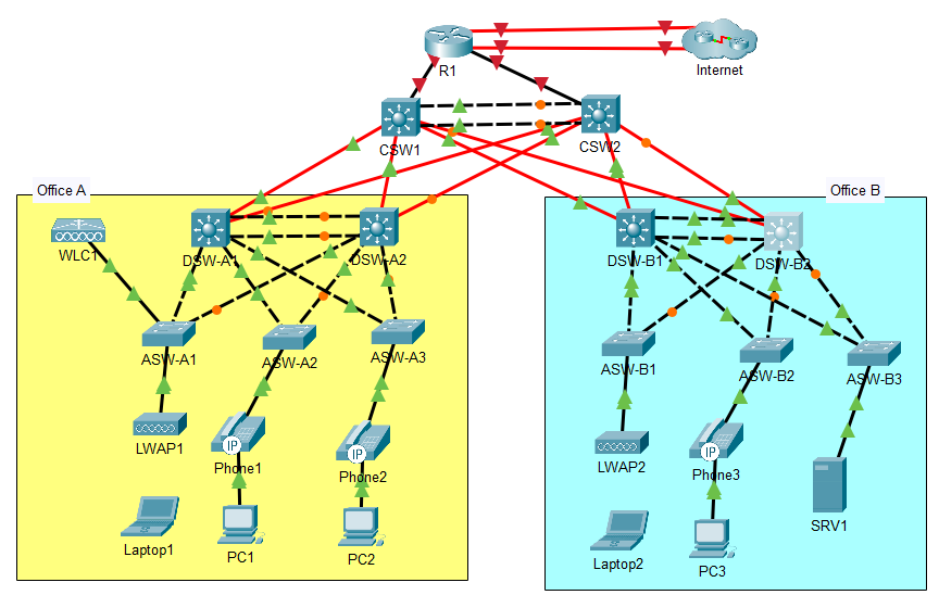
- Configure the following DHCP pools on R1 to make it serve as the DHCP server for hosts in Offices A and B. Exclude the first ten usable host addresses of each pool; they must not be leased to DHCP clients.
a. Pool: A-Mgmt
i. Subnet: 10.0.0.0/28
ii. Default gateway: 10.0.0.1
iii. Domain name: jeremysitlab.com
iv. DNS server: 10.5.0.4 (SRV1)
v. WLC: 10.0.0.7
b. Pool: A-PC
i. Subnet: 10.1.0.0/24
ii. Default gateway: 10.1.0.1
iii. Domain name: jeremysitlab.com
iv. DNS server: 10.5.0.4 (SRV1)
c. Pool: A-Phone
i. Subnet: 10.2.0.0/24
ii. Default gateway: 10.2.0.1
iii. Domain name: jeremysitlab.com
iv. DNS server: 10.5.0.4 (SRV1)
d. Pool: B-Mgmt
i. Subnet: 10.0.0.16/28
ii. Default gateway: 10.0.0.17
iii. Domain name: jeremysitlab.com
iv. DNS server: 10.5.0.4 (SRV1)
v. WLC: 10.0.0.7
e. Pool: B-PC
i. Subnet: 10.3.0.0/24
ii. Default gateway: 10.3.0.1
iii. Domain name: jeremysitlab.com
iv. DNS server: 10.5.0.4 (SRV1)
f. Pool: B-Phone
i. Subnet: 10.4.0.0/24
ii. Default gateway: 10.4.0.1
iii. Domain name: jeremysitlab.com
iv. DNS server: 10.5.0.4 (SRV1)
g. Pool: Wi-Fi
i. Subnet: 10.6.0.0/24
ii. Default gateway: 10.6.0.1
iii. Domain name: jeremysitlab.com
iv. DNS server: 10.5.0.4 (SRV1)
Create exclusions and configure Management DHCP Pool:
R1#conf t
R1(config)#ip dhcp excluded-address 10.0.0.1 10.0.0.10
R1(config)#ip dhcp excluded-address 10.1.0.1 10.1.0.10
R1(config)#ip dhcp excluded-address 10.2.0.1 10.2.0.10
R1(config)#ip dhcp excluded-address 10.0.0.17 10.0.0.26
R1(config)#ip dhcp excluded-address 10.3.0.1 10.3.0.10
R1(config)#ip dhcp excluded-address 10.4.0.1 10.4.0.10
R1(config)#ip dhcp excluded-address 10.6.0.1 10.6.0.10
R1(config)#ip dhcp pool A-Mgmt
R1(dhcp-config)#network 10.0.0.0 255.255.255.240
R1(dhcp-config)#default-router 10.0.0.1
R1(dhcp-config)#domain-name jeremysitlab.com
R1(dhcp-config)#dns-server 10.5.0.4
R1(dhcp-config)#option 43 ip 10.0.0.7
For the WLC, since AP1 is in the same broadcast domain as the WLC in Office A, we don't need to actually specify it, but for Office B's management network, it needs specified in the DHCP pool so AP2 can send a unicast message directly to it.
Configure the remaining pools on R1:
ip dhcp pool A-PC
network 10.1.0.0 255.255.255.0
default-router 10.1.0.1
dns-server 10.5.0.4
domain-name jeremysitlab.com

ip dhcp pool B-Mgmt
network 10.0.0.16 255.255.255.240
default-router 10.0.0.17
dns-server 10.5.0.4
domain-name jeremysitlab.com
option 43 ip 10.0.0.7

ip dhcp pool B-PC
network 10.3.0.0 255.255.255.0
default-router 10.3.0.1
dns-server 10.5.0.4
domain-name jeremysitlab.com

ip dhcp pool B-Phone
network 10.4.0.0 255.255.255.0
default-router 10.4.0.1
dns-server 10.5.0.4
domain-name jeremysitlab.com

ip dhcp pool Wi-Fi
network 10.6.0.0 255.255.255.0
default-router 10.6.0.1
dns-server 10.5.0.4
domain-name jeremysitlab.com
Configure IP Helpers
- Configure the Distribution switches to relay wired DHCP clients’ broadcast messages to R1’s Loopback0 IP address.
If you run:
R1(dhcp-config)#do show ip dhcp binding
IP address       Client-ID/              Lease expiration        Type
                 Hardware address
You don't see any leases. This is because clients broadcast DHCP requests won't reach R1. We need to configure the distribution switches to function as DHCP relay agents, forwarding clients broadcast messages to R1's loopback IP address, 10.0.0.76. To do that, we need to use the ip helper-address command on the interfaces that recieve clients broadcast DHCP messages, in this case the various SVIs on each switch (the layer 3 interface).
DSW-A1, DSW-A2:
interface vlan 10
 ip helper-address 10.0.0.76
interface vlan 20
 ip helper-address 10.0.0.76
interface vlan 40
 ip helper-address 10.0.0.76
interface vlan 99
 ip helper-address 10.0.0.76
DSW-B1, DSW-B2:
interface vlan 10
 ip helper-address 10.0.0.76
interface vlan 20
 ip helper-address 10.0.0.76
interface vlan 30
 ip helper-address 10.0.0.76
interface vlan 99
 ip helper-address 10.0.0.76
- Configure the following DNS entries on SRV1:
a. google.com = 172.253.62.100
b. youtube.com = 152.250.31.93
c. jeremysitlab.com = 66.235.200.145
d. www.jeremysitlab.com = jeremysitlab.com
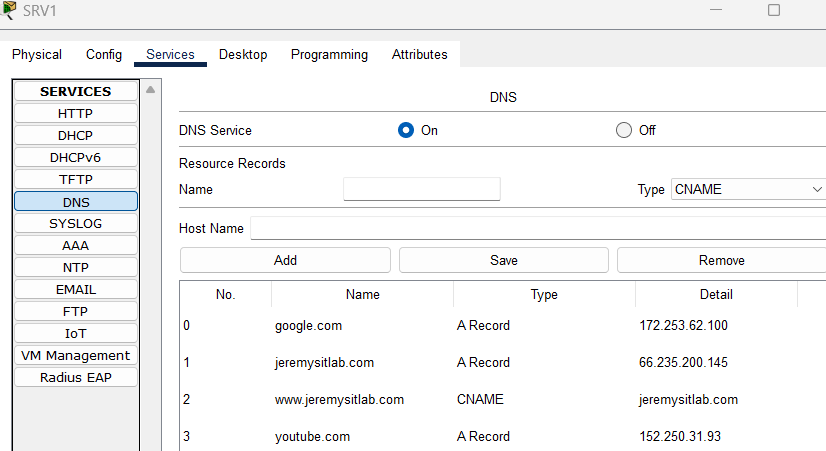
Test that DNS works from a PC.
Configure DNS server of Routers and Switches
- Configure all routers and switches to use domain name jeremysitlab.com and use SRV1 as their DNS server.
ip domain name jeremysitlab.com
ip name-server 10.5.0.4
Configure NTP Server
- Configure NTP on R1:
a. Make R1 a stratum 5 NTP server.
b. R1 should learn the time from NTP server 216.239.35.0.
c. NOTE: NTP takes a LONG time to sync, especially in Packet Tracer. After making the configurations, you can move on – don’t wait for the devices to sync.
R1(config)#ntp master 5
R1(config)#ntp server 216.239.35.0
- All Core, Distribution, and Access switches should use R1’s loopback interface as their NTP server.
a. Clients should authenticate R1 using key number 1 and the password ccna.
Create the NTP Authentication key (and trust it) on R1:
R1(config)#ntp authentication-key 1 md5 ccna
R1(config)#ntp trusted-key 1
Configure all of the remaining switches with:
ntp authentication-key 1 md5 ccna
ntp trusted-key 1
ntp server 10.0.0.76 key 1
Configure Syslog / SNMP
- Configure the SNMP community string SNMPSTRING on all routers and switches. The string should allow GET messages, but not SET messages. (This means it should be a read only string, and not a read write string)
Configure R1:
R1(config)#snmp-server community SNMPSTRING ro
%SNMP-5-WARMSTART: SNMP agent on host R1 is undergoing a warm start
With this configured, an SNMP server should be able to send SNMP GET messages to read information from this router. Configure the switches with the same (command included below)
- Configure Syslog on all routers and switches:
a. Send Syslog messages to SRV1. Messages of all severity levels should be logged.
b. Enable logging to the buffer. Reserve 8192 bytes of memory for the buffer.
R1(config)#logging 10.5.0.4
R1(config)#logging trap debugging
R1(config)#logging buffered 8192

R1(config)#do show logging
Syslog logging: enabled (0 messages dropped, 0 messages rate-limited,
          0 flushes, 0 overruns, xml disabled, filtering disabled)

No Active Message Discriminator.


No Inactive Message Discriminator.


    Console logging: level debugging, 17 messages logged, xml disabled,
          filtering disabled
    Monitor logging: level debugging, 17 messages logged, xml disabled,
          filtering disabled
    Buffer logging:  level debugging, 0 messages logged, xml disabled,
          filtering disabled

    Logging Exception size (4096 bytes)
    Count and timestamp logging messages: disabled
    Persistent logging: disabled

No active filter modules.

ESM: 0 messages dropped
    Trap logging: level debugging, 17 message lines logged
        Logging to 10.5.0.4  (udp port 514,  audit disabled,
             authentication disabled, encryption disabled, link up),
             0 message lines logged,
             0 message lines rate-limited,
             0 message lines dropped-by-MD,
             xml disabled, sequence number disabled
             filtering disabled
Log Buffer (8192 bytes):
Configure the remaining devices:
snmp-server community SNMPSTRING ro

logging 10.5.0.4
logging trap debugging
logging buffered 8192
logging 10.5.0.4
logging trap debugging
logging buffered 8192
do wr
Update Router Firmware via FTP
- Use FTP on R1 to download a new IOS version from SRV1: a. Configure R1’s default FTP credentials for accessing a server: username cisco, password cisco.
R1(config)#ip ftp username cisco
R1(config)#ip ftp password cisco
b. Use FTP to copy the file c2900-universalk9-mz.SPA.155-3.M4a.bin from SRV1 to R1’s flash drive.
R1(config)#do ping 10.5.0.4

Type escape sequence to abort.
Sending 5, 100-byte ICMP Echos to 10.5.0.4, timeout is 2 seconds:
!!!!!
Success rate is 100 percent (5/5), round-trip min/avg/max = 0/0/0 ms

R1(config)#do copy ftp flash
Address or name of remote host []? 10.5.0.4
Source filename []? c2900-universalk9-mz.SPA.155-3.M4a.bin
Destination filename [c2900-universalk9-mz.SPA.155-3.M4a.bin]?

Accessing ftp://10.5.0.4/c2900-universalk9-mz.SPA.155-3.M4a.bin...
[OK - 33591768 bytes]

33591768 bytes copied in 92.526 secs (38118 bytes/sec)
Confirm the image was copied:
R1(config)#do sh flash

System flash directory:
File  Length   Name/status
  3   33591768 c2900-universalk9-mz.SPA.151-4.M4.bin
  4   33591768 c2900-universalk9-mz.SPA.155-3.M4a.bin
  2   28282    sigdef-category.xml
  1   227537   sigdef-default.xml
[67439355 bytes used, 188304645 available, 255744000 total]
249856K bytes of processor board System flash (Read/Write)
Tell the router to boot from the new image and save the config. Here we checked the old version just to verify what it is:
R1(config)#boot system flash:c2900-universalk9-mz.SPA.155-3.M4a.bin
R1(config)#do wr
Building configuration...
[OK]

R1(config)#do sh version
Cisco IOS Software, C2900 Software (C2900-UNIVERSALK9-M), Version 15.1(4)M4, RELEASE SOFTWARE
c. Reboot R1 using the new IOS file, and then delete the old one from flash.
R1(config)#do reload
Proceed with reload? [confirm]
Confirm new version:
R1#sh ver
Cisco IOS Software, C2900 Software (C2900-UNIVERSALK9-M), Version 15.5(3)M4a, RELEASE SOFTWARE
Check and delete the old file:
R1#sh flash

System flash directory:
File  Length   Name/status
  3   33591768 c2900-universalk9-mz.SPA.151-4.M4.bin
  4   33591768 c2900-universalk9-mz.SPA.155-3.M4a.bin
  2   28282    sigdef-category.xml
  1   227537   sigdef-default.xml
[67439355 bytes used, 188304645 available, 255744000 total]
249856K bytes of processor board System flash (Read/Write)


R1#delete flash:c2900-universalk9-mz.SPA.151-4.M4.bin
Delete filename [c2900-universalk9-mz.SPA.151-4.M4.bin]?
Delete flash:/c2900-universalk9-mz.SPA.151-4.M4.bin? [confirm]

R1#sh flash

System flash directory:
File  Length   Name/status
  4   33591768 c2900-universalk9-mz.SPA.155-3.M4a.bin
  2   28282    sigdef-category.xml
  1   227537   sigdef-default.xml
[33847587 bytes used, 221896413 available, 255744000 total]
249856K bytes of processor board System flash (Read/Write)
Configure SSH on Routers / Switches
- Configure SSH for secure remote access on all routers and switches.
a. Use the largest modulus size for the RSA keys.
R1(config)#crypto key generate rsa
The name for the keys will be: R1.jeremysitlab.com
Choose the size of the key modulus in the range of 360 to 4096 for your
  General Purpose Keys. Choosing a key modulus greater than 512 may take
  a few minutes.

How many bits in the modulus [512]: 4096
% Generating 4096 bit RSA keys, keys will be non-exportable...[OK]
b. Allow SSHv2 connections only.
R1(config)#do sh ip ssh
*Mar 1 0:4:15.496: %SSH-5-ENABLED: SSH 1.99 has been enabled
SSH Enabled - version 1.99
1.99 isn't a real version of SSH, it just means that R1 can receive connections on version 1 or 2. Change this with:
R1(config)#ip ssh version 2
R1(config)#do sh ip ssh
SSH Enabled - version 2.0
c. Create standard ACL 1, only allowing packets sourced from Office A’s PCs subnet. Apply the ACL to all VTY lines to restrict SSH access.
d. Allow only SSH connections to the VTY lines.
e. Require users to log in with a local user account when connecting via SSH.
f. Configure synchronous logging on the VTY lines.
Create ACL:
R1(config)#access-list 1 permit 10.1.0.0 0.0.0.255
Configure and apply ACL:
R1(config)#line vty 0 15
R1(config-line)#access-class 1 in
R1(config-line)#transport input ssh
R1(config-line)#login local
R1(config-line)#logging synchronous
Configure the same for the rest of the devices with:
crypto key generate rsa 4096
ip ssh version 2
access-list 1 permit 10.1.0.0 0.0.0.255
line vty 0 15
 access-class 1 in
 transport input ssh
 login local
 logging synchronous
Confirm that SSH works from a PC in Office A, and doesn't work from a PC in Office B.
Configure Static NAT
- Configure static NAT on R1 to enable hosts on the Internet to access SRV1 via the IP address 203.0.113.113.
Configure the Static NAT:
R1(config)#ip nat inside source static 10.5.0.4 203.0.113.113

R1(config)#interface range g0/0/0,g0/1/0
R1(config-if-range)#ip nat outside
R1(config-if-range)#int range g0/0-1
R1(config-if-range)#ip nat inside
R1(config-if-range)#exit
Make sure you can ping google.com from SRV1
Configure Pool-based Dynamic PAT
- Configure pool-based dynamic PAT on R1 to enable hosts in the Office A PCs, Office A Phones, Office B PCs, Office B Phones, and Wi-Fi subnets to access the Internet.
a. Use standard ACL 2 to define the appropriate inside local address ranges in the following order:
i. Office A PCs: 10.1.0.0/24
ii. Office A Phones: 10.2.0.0/24
iii. Office B PCs: 10.3.0.0/24
iv. Office B Phones: 10.4.0.0/24
v. Wi-Fi: 10.6.0.0/24
Configure an ACL to define the range of inside local addresses that will be translated when communicating over the Internet:
R1(config)#access-list 2 permit 10.1.0.0 0.0.0.255
R1(config)#access-list 2 permit 10.2.0.0 0.0.0.255
R1(config)#access-list 2 permit 10.3.0.0 0.0.0.255
R1(config)#access-list 2 permit 10.4.0.0 0.0.0.255
R1(config)#access-list 2 permit 10.6.0.0 0.0.0.255
b. Define a range of inside global addresses called POOL1, specifying the range 203.0.113.200 to 203.0.113.207 with a /29 netmask.
R1(config)#ip nat pool POOL1 203.0.113.200 203.0.113.207 netmask 255.255.255.248
c. Map ACL 2 to POOL1 and enable PAT. Confirm that hosts can access the Internet by pinging jeremysitlab.com.
overload makes it PAT instead of regular dynamic NAT:
R1(config)#ip nat inside source list 2 pool POOL1 overload
d. Verify that Internet link failover works by disabling R1’s G0/0/0 interface and pinging again.
i. You will need to remove and re-configure the OSPF default-information originate command for this to work. In real Cisco routers, you can configure the default-information originate always command that supports failover like this, but the command isn’t available in Packet Tracer.
Disable int g0/0/0:
R1(config)#int g0/0/0
R1(config-if)#shut
Remove/re-add the default-information originate from OSPF. You would not have to do this on a real Cisco device where default-information originate always was set:
R1(config-if)#router ospf 1
R1(config-router)#no default-information originate
See the floating static route with AD 2 took over:
R1(config-router)#do sh ip route
S*   0.0.0.0/0 [2/0] via 203.0.113.5
Confirm it worked by pinging jeremysitlab.com from your test PC.
ii. Re-enable G0/0/0 (and remove and re-configure default-information originate once again).
R1(config-router)#int g0/0/0
R1(config-if)#no shut

R1(config-if)#router ospf 1
R1(config-router)#no default-information originate
R1(config-router)#default-information originate
CDP / LLDP
- Disable CDP on all devices and enable LLDP instead.
a. Disable LLDP Tx on each Access switch’s access port (F0/1).
R1, Core and Distribution switches:
no cdp run
lldp run
Access switches:
no cdp run
lldp run
interface f0/1
 no lldp transmit