IP Addresses, Layer-3 EtherChannel, HSRP
Configure IP Addressing on Router
- Configure the following IP addresses on R1’s interfaces and enable them (remember that router interfaces are shut down by default):
a. G0/0/0: DHCP client
b. G0/1/0: DHCP client
c. G0/0: 10.0.0.33/30
d. G0/1: 10.0.0.37/30
e. Loopback0: 10.0.0.76/32
R1#conf t
R1(config)#int range g0/0/0,g0/1/0
R1(config-if-range)#ip add dhcp
R1(config-if-range)#no shutdown
R1(config-if-range)#int g0/0
R1(config-if)#ip add 10.0.0.33 255.255.255.252
R1(config-if)#no shut
R1(config-if)#int g0/1
R1(config-if)#ip add 10.0.0.37 255.255.255.252
R1(config-if)#no shut
R1(config-if)#int l0
R1(config-if)#ip add 10.0.0.76 255.255.255.255
Confirm the addressing:
R1(config-if)#do show ip int br
Interface              IP-Address      OK? Method Status                Protocol
GigabitEthernet0/0     10.0.0.33       YES manual up                    up
GigabitEthernet0/1     10.0.0.37       YES manual up                    up
GigabitEthernet0/2     unassigned      YES unset  administratively down down
GigabitEthernet0/0/0   203.0.113.2     YES DHCP   up                    up
GigabitEthernet0/1/0   203.0.113.6     YES DHCP   up                    up
Loopback0              10.0.0.76       YES manual up                    up
Vlan1                  unassigned      YES unset  administratively down down
- Enable IPv4 routing on all Core and Distribution switches.
CSW1#conf t
Enter configuration commands, one per line.  End with CNTL/Z.
CSW1(config)#ip routing
- Create a Layer-3 EtherChannel between CSW1 and CSW2 using a Cisco-proprietary protocol. Both switches should actively try to form an EtherChannel. Configure the following IP addresses:
a. CSW1 PortChannel1: 10.0.0.41/30
b. CSW2 PortChannel1: 10.0.0.42/30
Confirm the interfaces needed for the port channel with cdp:
CSW1(config)#do sh cdp nei
Capability Codes: R - Router, T - Trans Bridge, B - Source Route Bridge
                  S - Switch, H - Host, I - IGMP, r - Repeater, P - Phone
Device ID    Local Intrfce   Holdtme    Capability   Platform    Port ID
DSW-B1       Gig 1/1/3        130                    3650        Gig 1/1/1
DSW-A1       Gig 1/1/1        130                    3650        Gig 1/1/1
DSW-A2       Gig 1/1/2        130                    3650        Gig 1/1/1
DSW-B2       Gig 1/1/4        130                    3650        Gig 1/1/1
CSW2         Gig 1/0/2        158                    3650        Gig 1/0/2
CSW2         Gig 1/0/3        158                    3650        Gig 1/0/3
R1           Gig 1/0/1        161            R       C2900       Gig 0/0
Select the interfaces, make them routed ports with no switchport, and enable the EtherChannel for PaGP with mode desirable:
CSW1(config)#int range g1/0/2-3
CSW1(config-if-range)#no switchport
CSW1(config-if-range)#channel-group 1 mode desirable
Configure an IP Address on the Port Channel:
CSW1(config-if-range)#int po1
CSW1(config-if)#ip add 10.0.0.41 255.255.255.252
Configure CSW2:
CSW2(config)#int range g1/0/2-3
CSW2(config-if-range)#no switchport
CSW2(config-if-range)#channel-group 1 mode desirable
CSW2(config-if-range)#int port-channel 1
CSW2(config-if)#ip add 10.0.0.42 255.255.255.252
Check the status of the Ether Channel:
CSW2(config-if)#do sh etherchannel summary
Flags:  D - down        P - in port-channel
        I - stand-alone s - suspended
        H - Hot-standby (LACP only)
        R - Layer3      S - Layer2
        U - in use      f - failed to allocate aggregator
        u - unsuitable for bundling
        w - waiting to be aggregated
        d - default port


Number of channel-groups in use: 1
Number of aggregators:           1

Group  Port-channel  Protocol    Ports
------+-------------+-----------+----------------------------------------------

1      Po1(RU)           PAgP   Gig1/0/2(P) Gig1/0/3(P)
Test by pinging CSW1:
CSW2(config-if)#do ping 10.0.0.41

Type escape sequence to abort.
Sending 5, 100-byte ICMP Echos to 10.0.0.41, timeout is 2 seconds:
!!!!!
Success rate is 100 percent (5/5), round-trip min/avg/max = 0/0/0 ms
- Configure the following IP addresses on CSW1. Disable all unused interfaces.
a. G1/0/1: 10.0.0.34/30
b. G1/1/1: 10.0.0.45/30
c. G1/1/2: 10.0.0.49/30
d. G1/1/3: 10.0.0.53/30
e. G1/1/4: 10.0.0.57/30
f. Loopback0: 10.0.0.77/32
interface g1/0/1
no switchport
ip address 10.0.0.34 255.255.255.252
interface g1/1/1
no switchport
ip address 10.0.0.45 255.255.255.252
interface g1/1/2
no switchport
ip address 10.0.0.49 255.255.255.252
interface g1/1/3
no switchport
ip address 10.0.0.53 255.255.255.252
interface g1/1/4
no switchport
ip address 10.0.0.57 255.255.255.252
interface loopback0
ip address 10.0.0.77 255.255.255.255
interface range g1/0/4-24
shutdown
- Configure the following IP addresses on CSW2. Disable all unused interfaces.
a. G1/0/1: 10.0.0.38/30
b. G1/1/1: 10.0.0.61/30
c. G1/1/2: 10.0.0.65/30
d. G1/1/3: 10.0.0.69/30
e. G1/1/4: 10.0.0.73/30
f. Loopback0: 10.0.0.78/32
interface g1/0/1
no switchport
ip address 10.0.0.38 255.255.255.252
interface g1/1/1
no switchport
ip address 10.0.0.61 255.255.255.252
interface g1/1/2
no switchport
ip address 10.0.0.65 255.255.255.252
interface g1/1/3
no switchport
ip address 10.0.0.69 255.255.255.252
interface g1/1/4
no switchport
ip address 10.0.0.73 255.255.255.252
interface loopback0
ip address 10.0.0.78 255.255.255.255
interface range g1/0/4-24
shutdown
- Configure the following IP addresses on DSW-A1:
a. G1/1/1: 10.0.0.46/30
b. G1/1/2: 10.0.0.62/30
c. Loopback0: 10.0.0.79/32
conf t
interface g1/1/1
no switchport
ip address 10.0.0.46 255.255.255.252
interface g1/1/2
no switchport
ip address 10.0.0.62 255.255.255.252
interface loopback0
ip address 10.0.0.79 255.255.255.255
- Configure the following IP addresses on DSW-A2:
a. G1/1/1: 10.0.0.50/30
b. G1/1/2: 10.0.0.66/30
c. Loopback0: 10.0.0.80/32
conf t
interface g1/1/1
no switchport
ip address 10.0.0.50 255.255.255.252
interface g1/1/2
no switchport
ip address 10.0.0.66 255.255.255.252
interface loopback0
ip address 10.0.0.80 255.255.255.255
- Configure the following IP addresses on DSW-B1:
a. G1/1/1: 10.0.0.54/30
b. G1/1/2: 10.0.0.70/30
c. Loopback0: 10.0.0.81/32
conf t
interface g1/1/1
no switchport
ip address 10.0.0.54 255.255.255.252
interface g1/1/2
no switchport
ip address 10.0.0.70 255.255.255.252
interface loopback0
ip address 10.0.0.81 255.255.255.255
- Configure the following IP addresses on DSW-B2:
a. G1/1/1: 10.0.0.58/30
b. G1/1/2: 10.0.0.74/30
c. Loopback0: 10.0.0.82/32
conf t
interface g1/1/1
no switchport
ip address 10.0.0.58 255.255.255.252
interface g1/1/2
no switchport
ip address 10.0.0.74 255.255.255.252
interface loopback0
ip address 10.0.0.82 255.255.255.255
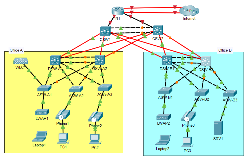
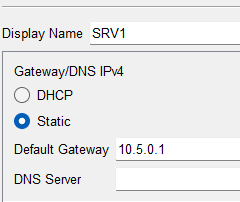
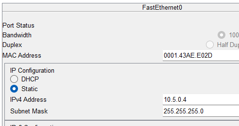
- Manually configure SRV1’s IP settings:
a. Default Gateway: 10.5.0.1
b. IPv4 Address: 10.5.0.4
c. Subnet Mask: 255.255.255.0
Configure IP Addressing on Switch Ports
- Configure the following management IP addresses on the Access switches (interface VLAN 99), and configure the appropriate subnet’s first usable address as the default gateway.
a. ASW-A1: 10.0.0.4/28
b. ASW-A2: 10.0.0.5/28
c. ASW-A3: 10.0.0.6/28
d. ASW-B1: 10.0.0.20/28
e. ASW-B2: 10.0.0.21/28
f. ASW-B3: 10.0.0.22/28
Set for all of the access switches like such:
ASW-A1(config)#ip default-gateway 10.0.0.1
ASW-A1(config)#interface vlan 99
ASW-A1(config-if)#ip add 10.0.0.4 255.255.255.240
ASW-A1(config-if)#do wr
Configure HSRP
- Configure HSRPv2 group 1 for Office A’s Management subnet (VLAN 99). Make DSW-A1 the Active router by increasing its priority to 5 above the default, and enable preemption on DSW-A1.
a. Subnet: 10.0.0.0/28
b. VIP: 10.0.0.1
c. DSW-A1: 10.0.0.2
d. DSW-A2: 10.0.0.3
Configure DSW-A1
DSW-A1(config-if)#int vlan 99
DSW-A1(config-if)#ip add 10.0.0.2 255.255.255.240
DSW-A1(config-if)#standby ver 2
DSW-A1(config-if)#standby 1 ip 10.0.0.1
DSW-A1(config-if)#
%HSRP-6-STATECHANGE: Vlan99 Grp 1 state Init -> Init

DSW-A1(config-if)#standby 1 priority 105
DSW-A1(config-if)#standby 1 preempt
DSW-A1(config-if)#
%HSRP-6-STATECHANGE: Vlan99 Grp 1 state Speak -> Standby

%HSRP-6-STATECHANGE: Vlan99 Grp 1 state Standby -> Active
The preempt command above was used so that the switch will always be the active switch as long as it is up and running. Increasing the priority ensured that DSW-A1 becomes the Active router.
Configure DSW-A2
DSW-A2(config-if)#int vlan 99
DSW-A2(config-if)#ip add 10.0.0.3 255.255.255.240
DSW-A2(config-if)#standby ver 2
DSW-A2(config-if)#standby 1 ip 10.0.0.1
DSW-A2(config-if)#
%HSRP-6-STATECHANGE: Vlan99 Grp 1 state Init -> Init

DSW-A2(config-if)#
%HSRP-6-STATECHANGE: Vlan99 Grp 1 state Speak -> Standby
We can leave A2 at the default priority since we already raised DSW-A1’s priority. There’s no need to configure preemption on the standby router, although you can use the command if you want to – it won’t do any harm.
- Configure HSRPv2 group 2 for Office A’s PCs subnet (VLAN 10). Make DSW-A1 the Active router by increasing its priority to 5 above the default (which is 100), and enable preemption on DSW-A1.
a. Subnet: 10.1.0.0/24
b. VIP: 10.1.0.1
c. DSW-A1: 10.1.0.2
d. DSW-A2: 10.1.0.3
DSW-A1:
DSW-A1(config-if)#interface vlan 10
DSW-A1(config-if)#ip address 10.1.0.2 255.255.255.0
DSW-A1(config-if)#standby ver 2
DSW-A1(config-if)#standby 2 ip 10.1.0.1
DSW-A1(config-if)#standby 2 pri 105
DSW-A1(config-if)#standby 2 preempt
DSW-A2:
DSW-A2(config-if)#int vlan 10
DSW-A2(config-if)#ip add 10.1.0.3 255.255.255.0
DSW-A2(config-if)#standby ver 2
DSW-A2(config-if)#standby 2 ip 10.1.0.1
- Configure HSRPv2 group 3 for Office A’s Phones subnet (VLAN 20). Make DSW-A2 the Active router by increasing its priority to 5 above the default, and enable preemption on DSW-A2.
a. Subnet: 10.2.0.0/24
b. VIP: 10.2.0.1
c. DSW-A1: 10.2.0.2
d. DSW-A2: 10.2.0.3
DSW-A2(config-if)#int vlan 20
DSW-A2(config-if)#ip add 10.2.0.3 255.255.255.0
DSW-A2(config-if)#standby ver 2
DSW-A2(config-if)#standby 3 ip 10.2.0.1
DSW-A2(config-if)#standby 3 pri 105
DSW-A2(config-if)#standby 3 preempt
DSW-A1:
interface vlan 20
ip add 10.2.0.2 255.255.255.0
standby ver 2
standby 3 ip 10.2.0.1
- Configure HSRPv2 group 4 for Office A’s Wi-Fi subnet (VLAN 40). Make DSW-A2 the Active router by increasing its priority to 5 above the default, and enable preemption on DSW-A2.
a. Subnet: 10.6.0.0/24
b. VIP: 10.6.0.1
c. DSW-A1: 10.6.0.2
d. DSW-A2: 10.6.0.3
DSW-A2(config-if)#int vlan 40
DSW-A2(config-if)#ip add 10.6.0.3 255.255.255.0
DSW-A2(config-if)#standby ver 2
DSW-A2(config-if)#standby 4 ip 10.6.0.1
DSW-A2(config-if)#standby 4 pri 105
DSW-A2(config-if)#standby 4 preempt
DSW-A1:
DSW-A1(config-if)#int vlan 40
DSW-A1(config-if)#ip add 10.6.0.2 255.255.255.0
DSW-A1(config-if)#standby ver 2
DSW-A1(config-if)#standby 4 ip 10.6.0.1
- Configure HSRPv2 group 1 for Office B’s Management subnet (VLAN 99). Make DSW-B1 the Active router by increasing its priority to 5 above the default, and enable preemption on DSW-B1.
a. Subnet: 10.0.0.16/28
b. VIP: 10.0.0.17
c. DSW-B1: 10.0.0.18
d. DSW-B2: 10.0.0.19 - Configure HSRPv2 group 2 for Office B’s PCs subnet (VLAN 10). Make DSW-B1 the Active router by increasing its priority to 5 above the default, and enable preemption on DSW-B1.
a. Subnet: 10.3.0.0/24
b. VIP: 10.3.0.1
c. DSW-B1: 10.3.0.2
d. DSW-B2: 10.3.0.3 - Configure HSRPv2 group 3 for Office B’s Phones subnet (VLAN 20). Make DSW-B2 the Active router by increasing its priority to 5 above the default, and enable preemption on DSW-B2.
a. Subnet: 10.4.0.0/24
b. VIP: 10.4.0.1
c. DSW-B1: 10.4.0.2
d. DSW-B2: 10.4.0.3 - Configure HSRPv2 group 4 for Office B’s Servers subnet (VLAN 30). Make DSW-B2 the Active router by increasing its priority to 5 above the default, and enable preemption on DSW-B2.
a. Subnet: 10.5.0.0/24
b. VIP: 10.5.0.1
c. DSW-B1: 10.5.0.2
d. DSW-B2: 10.5.0.3
Configure DSW-B1:
interface vlan99
ip address 10.0.0.18 255.255.255.240
standby ver 2
standby 1 ip 10.0.0.17
standby 1 pri 105
standby 1 preempt

interface vlan10
ip address 10.3.0.2 255.255.255.0
standby ver 2
standby 2 ip 10.3.0.1
standby 2 pri 105
standby 2 preempt

int vlan20
ip add 10.4.0.2 255.255.255.0
standby ver 2
standby 3 ip 10.4.0.1

int vlan 30
ip add 10.5.0.2 255.255.255.0
standby ver 2
standby 4 ip 10.5.0.1
Configure DSW-B2:
interface vlan99
ip address 10.0.0.19 255.255.255.240
standby ver 2
standby 1 ip 10.0.0.17

interface vlan10
ip address 10.3.0.3 255.255.255.0
standby ver 2
standby 2 ip 10.3.0.1

int vlan20
ip add 10.4.0.3 255.255.255.0
standby ver 2
standby 3 ip 10.4.0.1
standby 3 pri 105
standby 3 preempt

int vlan 30
ip add 10.5.0.3 255.255.255.0
standby ver 2
standby 4 ip 10.5.0.1
standby 4 pri 105
standby 4 preempt